
Mục lục
Xem thêm:
Xin chào mọi người!
Hôm nay chúng ta sẽ cùng tìm hiểu về màn hình GLCD 128x64 và cách thức giao tiếp với nó với vđk atmega 16 trên bộ KIT.
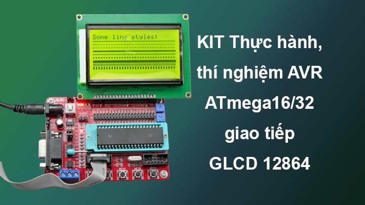
LCD 12864 là Graphic LCD (G-LCD) sử dụng IC Driver ST7920. Đây là loại màn hình phổ biến và được sử dụng rộng rãi. LCD Graphic 128x64 thích hợp cho các ứng dụng hiển thị hình ảnh, chữ ở 1 diện tích lớn, màn hình có độ bền cao, nhiều code mẫu và dễ sử dụng thích hợp cho những người mới học và làm dự án.
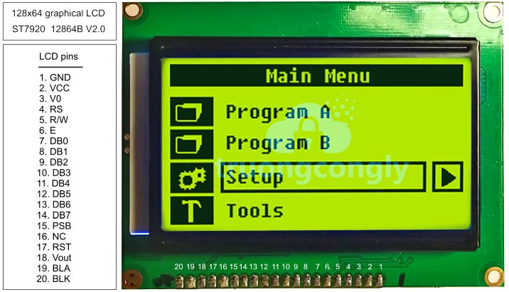
| Pin No | Symbol | Description | Function |
| 1 | VSS | GROUND | 0V (GND) |
| 2 | VDD | POWER SUPPLY FOR LOGIC CIRCUIT | +5V |
| 3 | V0/VDD/NC | LCD CONTRAST ADJUSTMENT OR LCD VOLTAGE OR NC | |
| 4 | D/I | INSTRUCTION/DATA REGISTER SELECTON | D/I=0: INSTRUCTION REGISTER D/I=1: DATA REGISTER |
| 5 | R/W | READ/WRITE SELECTION | R/W=0; REGISTER WRITE R/W=1: REGISTER READ |
| 6 | E | ENABLE SIGNAL | |
| 7 | DB0 | DATA INPUT/OUTPUT LINES | 8 BIT: DB0-DB7 |
| 8 | DB1 | ||
| 9 | DB2 | ||
| 10 | DB3 | ||
| 11 | DB4 | ||
| 12 | DB5 | ||
| 13 | DB6 | ||
| 14 | DB7 | ||
| 15 | PSB | SERIAL/PARALLEL SELECTION | PSB=0: SERIAL MODE, PSB=1: 8/4BIT PARALLEL BUS MODE |
| 16 | NC | ||
| 17 | RST | RESET SIGNAL | |
| 18 | VEE/NC | LCD DRIVE VOLTAGE/NC | RSTB=0, DISPLAY OFF, DISPLAY FROM LINE 0. |
| 19 | A | SUPPLY VOLTAGE FOR LED + | +5V |
| 20 | K | SUPPLY VOLTAGE FOR LED - | 0V |
Link sản phẩm:
Thông Số Kỹ Thuật:
- Điện áp hoạt động: 5VDC
- Độ phân giải: 128x64 điểm ảnh
- Các chuẩn giao tiếp: Song song 8 bit, song song 4 bit, và giao tiếp nối tiếp.
- IC Driver: ST7920.
Trong môi trường lập trình CodeVisionAVR, đã tích hợp sẵn thư viện cho GLCD, điều này giúp chúng ta chỉ cần khai báo các hàm và sử dụng chúng một cách dễ dàng. Ngoài ra, CodeVisionAVR cũng cung cấp các công cụ để thay đổi và cài đặt chân giao tiếp trong phần cài đặt của dự án. Quá trình này thường diễn ra như sau:

B1: Tạo mới Project dùng CodeWizardAVR
- Vào File --> New --> Project
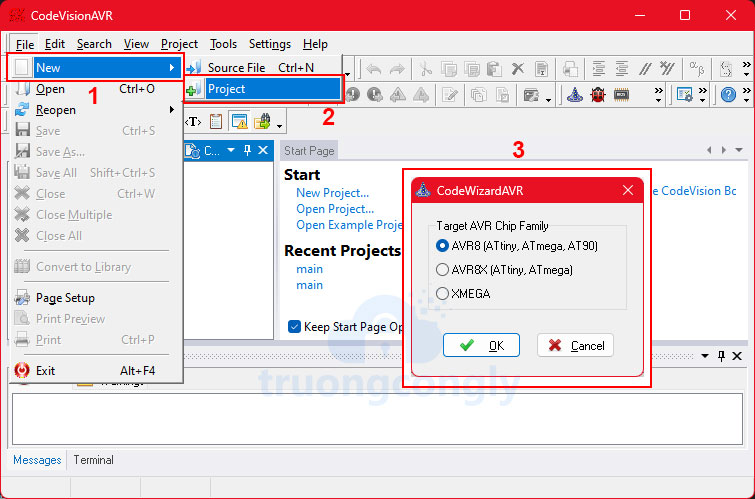
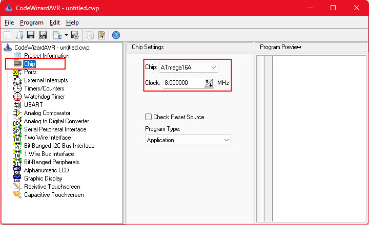
B2: Chọn Chip và xung Clock
- Chọn thẻ Chip sau đó chọn chip ATmega16A và clock là 8MHz
B3: Cấu hình cho GLCD
- Chọn thẻ Graphic Display sau đó chọn Display Type là ST7920 128x64, 8-bit Bus /RST PSB=1.
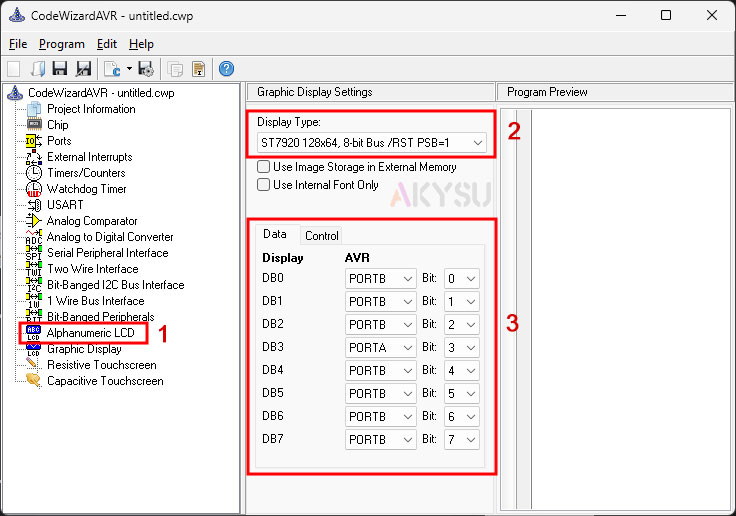
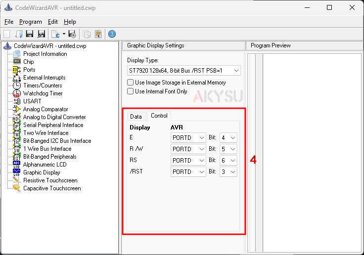
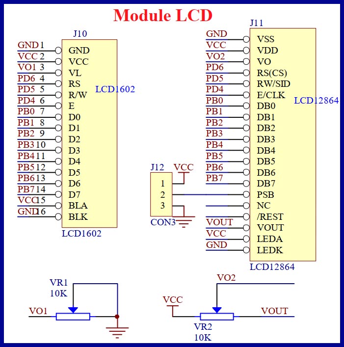
Các bạn chọn các chân giao tiếp với GLCD tươg ứng, chú ý là không được sử dụng các chân đã set cho các kết nối khác, ở trên sử dụng PORTD và PORTB của ATmega16 làm ví dụ.
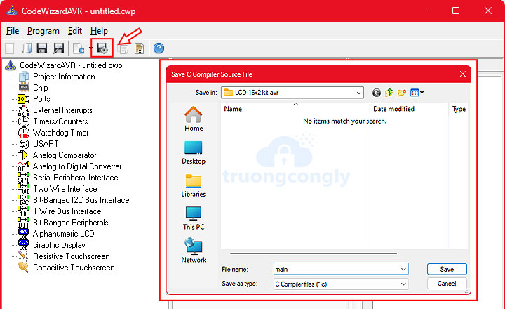
B4: Bấm nút Generate program save and exit để lưu và tạo code.
Ngoài thư viện của chip ta sẽ chèn thêm 2 thư viện là glcd.h và delay.h cả hai thư viện này đều dùng cho giao tiếp GLCD.
Một số hàm giao tiếp GLCD trong thư viện glcd.h:
/* Set horizontal justification: 1 pixels and
		   vertical justification: 1 pixel */
		glcd_settextjustify(1, 1);
		glcd_setfont(font5x7);
		glcd_outtextf("thegioiic.com:");
		/* Draw various styles of lines */
		/* Line thickness: 1 pixel */
		glcd_line(0, 10, 127, 10);
		glcd_setlinestyle(1, GLCD_LINE_DOT_SMALL);
		glcd_line(0, 15, 127, 15);
		glcd_setlinestyle(1, GLCD_LINE_DOT_LARGE);
		glcd_line(0, 20, 127, 20);
		/* Line thickness: 2 pixels */
		glcd_setlinestyle(2, GLCD_LINE_SOLID);
		glcd_line(0, 25, 127, 25);
		glcd_setlinestyle(2, GLCD_LINE_DOT_SMALL);
		glcd_line(0, 30, 127, 30);
		glcd_setlinestyle(2, GLCD_LINE_DOT_LARGE);
		glcd_line(0, 35, 127, 35);
		/* Line thickness: 4 pixels */
		glcd_setlinestyle(4, GLCD_LINE_SOLID);
		glcd_line(0, 40, 127, 40);
		glcd_setlinestyle(4, GLCD_LINE_DOT_SMALL);
		glcd_line(0, 45, 127, 45);
		glcd_setlinestyle(4, GLCD_LINE_DOT_LARGE);
		glcd_line(0, 50, 127, 50);
		/* 3 seconds delay */
		delay_ms(3000);
		/* Clear display */
		glcd_clear();
		/* Fill the hexagon with solid fill */
		glcd_floodfill(48, 24, 1);
		/* Clear display */
		glcd_clear();
		/* Draw a circle with line thickness: 1 pixel */
		glcd_circle(21, 23, 20);
		/* Draw an arc of a circle with line thickness: 1 pixel */
		glcd_arc(21, 23, 0, 120, 15);
		/* Draw a circle with line thickness: 3 pixels */
		glcd_setlinestyle(3, GLCD_LINE_SOLID);
		glcd_circle(63, 23, 20);
		/* Draw an arc of a circle with line thickness: 3 pixels */
		glcd_arc(63, 23, 0, 210, 15);
		glcd_outtextxyf(0, 47, "Circles & arcs");
		/* 3 seconds delay */
		delay_ms(3000);
		/* Clear display */
		glcd_clear();
		glcd_setcolor(1);
		glcd_setbkcolor(0);
		/* Draw a rectangle with line thickness: 1 pixel
		   and solid line */
		glcd_setlinestyle(1, GLCD_LINE_SOLID);
		glcd_rectrel(0, 0, 40, 25);
		/* Draw a rectangle with line thickness: 3 pixel
		   and dotted line */
		glcd_setlinestyle(3, GLCD_LINE_DOT_LARGE);
		glcd_rectrel(42, 0, 40, 25);
		glcd_outtextxyf(0, 47, "Rectangles &nfilled bar");
		/* 3 seconds delay */
		delay_ms(3000);
		/* Clear display */
		glcd_clear();
		/* Draw rounded rectangle */
		glcd_rectround(5, 5, 74, 38, 8);
		glcd_outtextxyf(16, 16, "Rounded");
		glcd_outtextxyf(16, 24, "rectangle");
		/* 3 seconds delay */
		delay_ms(3000);
		/* Clear display */
		glcd_clear();
		/* Set line thickness: 1 pixel */
		glcd_setlinestyle(1, GLCD_LINE_SOLID);
		/* Draw filled pie slice */
		glcd_outtextf("Pienslice:");
		glcd_pieslice(60, 23, 30, 300, 20);
		/* 3 seconds delay */
		delay_ms(3000);
		/* Clear display */
		glcd_clear();
Code mẫu full:
/*******************************************************
*
Author :truongcongly.com
Chip type : ATmega16A
Program type : Application
AVR Core Clock frequency: 8.000000 MHz
Memory model : Small
External RAM size : 0
Data Stack size : 256
*******************************************************/
#include <mega16a.h>
#include <delay.h>
// Graphic Display functions
#include <glcd.h>
// Font used for displaying text
// on the graphic display
#include <font5x7.h>
// Declare your global variables here
void main(void)
{
// Declare your local variables here
// Variable used to store graphic display
// controller initialization data
GLCDINIT_t glcd_init_data;
// Input/Output Ports initialization
// Port A initialization
// Function: Bit7=In Bit6=In Bit5=In Bit4=In Bit3=In Bit2=In Bit1=In Bit0=In
DDRA = (0 << DDA7) | (0 << DDA6) | (0 << DDA5) | (0 << DDA4) | (0 << DDA3) | (0 << DDA2) | (0 << DDA1) | (0 << DDA0);
// State: Bit7=T Bit6=T Bit5=T Bit4=T Bit3=T Bit2=T Bit1=T Bit0=T
PORTA = (0 << PORTA7) | (0 << PORTA6) | (0 << PORTA5) | (0 << PORTA4) | (0 << PORTA3) | (0 << PORTA2) | (0 << PORTA1) | (0 << PORTA0);
// Port B initialization
// Function: Bit7=In Bit6=In Bit5=In Bit4=In Bit3=In Bit2=In Bit1=In Bit0=In
DDRB = (0 << DDB7) | (0 << DDB6) | (0 << DDB5) | (0 << DDB4) | (0 << DDB3) | (0 << DDB2) | (0 << DDB1) | (0 << DDB0);
// State: Bit7=T Bit6=T Bit5=T Bit4=T Bit3=T Bit2=T Bit1=T Bit0=T
PORTB = (0 << PORTB7) | (0 << PORTB6) | (0 << PORTB5) | (0 << PORTB4) | (0 << PORTB3) | (0 << PORTB2) | (0 << PORTB1) | (0 << PORTB0);
// Port C initialization
// Function: Bit7=In Bit6=In Bit5=In Bit4=In Bit3=In Bit2=In Bit1=In Bit0=In
DDRC = (0 << DDC7) | (0 << DDC6) | (0 << DDC5) | (0 << DDC4) | (0 << DDC3) | (0 << DDC2) | (0 << DDC1) | (0 << DDC0);
// State: Bit7=T Bit6=T Bit5=T Bit4=T Bit3=T Bit2=T Bit1=T Bit0=T
PORTC = (0 << PORTC7) | (0 << PORTC6) | (0 << PORTC5) | (0 << PORTC4) | (0 << PORTC3) | (0 << PORTC2) | (0 << PORTC1) | (0 << PORTC0);
// Port D initialization
// Function: Bit7=In Bit6=In Bit5=In Bit4=In Bit3=In Bit2=In Bit1=In Bit0=In
DDRD = (0 << DDD7) | (0 << DDD6) | (0 << DDD5) | (0 << DDD4) | (0 << DDD3) | (0 << DDD2) | (0 << DDD1) | (0 << DDD0);
// State: Bit7=T Bit6=T Bit5=T Bit4=T Bit3=T Bit2=T Bit1=T Bit0=T
PORTD = (0 << PORTD7) | (0 << PORTD6) | (0 << PORTD5) | (0 << PORTD4) | (0 << PORTD3) | (0 << PORTD2) | (0 << PORTD1) | (0 << PORTD0);
// Timer/Counter 0 initialization
// Clock source: System Clock
// Clock value: Timer 0 Stopped
// Mode: Normal top=0xFF
// OC0 output: Disconnected
TCCR0 = (0 << WGM00) | (0 << COM01) | (0 << COM00) | (0 << WGM01) | (0 << CS02) | (0 << CS01) | (0 << CS00);
TCNT0 = 0x00;
OCR0 = 0x00;
// Timer/Counter 1 initialization
// Clock source: System Clock
// Clock value: Timer1 Stopped
// Mode: Normal top=0xFFFF
// OC1A output: Disconnected
// OC1B output: Disconnected
// Noise Canceler: Off
// Input Capture on Falling Edge
// Timer1 Overflow Interrupt: Off
// Input Capture Interrupt: Off
// Compare A Match Interrupt: Off
// Compare B Match Interrupt: Off
TCCR1A = (0 << COM1A1) | (0 << COM1A0) | (0 << COM1B1) | (0 << COM1B0) | (0 << WGM11) | (0 << WGM10);
TCCR1B = (0 << ICNC1) | (0 << ICES1) | (0 << WGM13) | (0 << WGM12) | (0 << CS12) | (0 << CS11) | (0 << CS10);
TCNT1H = 0x00;
TCNT1L = 0x00;
ICR1H = 0x00;
ICR1L = 0x00;
OCR1AH = 0x00;
OCR1AL = 0x00;
OCR1BH = 0x00;
OCR1BL = 0x00;
// Timer/Counter 2 initialization
// Clock source: System Clock
// Clock value: Timer2 Stopped
// Mode: Normal top=0xFF
// OC2 output: Disconnected
ASSR = 0 << AS2;
TCCR2 = (0 << PWM2) | (0 << COM21) | (0 << COM20) | (0 << CTC2) | (0 << CS22) | (0 << CS21) | (0 << CS20);
TCNT2 = 0x00;
OCR2 = 0x00;
// Timer(s)/Counter(s) Interrupt(s) initialization
TIMSK = (0 << OCIE2) | (0 << TOIE2) | (0 << TICIE1) | (0 << OCIE1A) | (0 << OCIE1B) | (0 << TOIE1) | (0 << OCIE0) | (0 << TOIE0);
// External Interrupt(s) initialization
// INT0: Off
// INT1: Off
// INT2: Off
MCUCR = (0 << ISC11) | (0 << ISC10) | (0 << ISC01) | (0 << ISC00);
MCUCSR = (0 << ISC2);
// USART initialization
// USART disabled
UCSRB = (0 << RXCIE) | (0 << TXCIE) | (0 << UDRIE) | (0 << RXEN) | (0 << TXEN) | (0 << UCSZ2) | (0 << RXB8) | (0 << TXB8);
// Analog Comparator initialization
// Analog Comparator: Off
// The Analog Comparator's positive input is
// connected to the AIN0 pin
// The Analog Comparator's negative input is
// connected to the AIN1 pin
ACSR = (1 << ACD) | (0 << ACBG) | (0 << ACO) | (0 << ACI) | (0 << ACIE) | (0 << ACIC) | (0 << ACIS1) | (0 << ACIS0);
SFIOR = (0 << ACME);
// ADC initialization
// ADC disabled
ADCSRA = (0 << ADEN) | (0 << ADSC) | (0 << ADATE) | (0 << ADIF) | (0 << ADIE) | (0 << ADPS2) | (0 << ADPS1) | (0 << ADPS0);
// SPI initialization
// SPI disabled
SPCR = (0 << SPIE) | (0 << SPE) | (0 << DORD) | (0 << MSTR) | (0 << CPOL) | (0 << CPHA) | (0 << SPR1) | (0 << SPR0);
// TWI initialization
// TWI disabled
TWCR = (0 << TWEA) | (0 << TWSTA) | (0 << TWSTO) | (0 << TWEN) | (0 << TWIE);
// Graphic Display Controller initialization
// The ST7920 connections are specified in the
// Project|Configure|C Compiler|Libraries|Graphic Display menu:
// DB0 - PORTB Bit 0
// DB1 - PORTB Bit 1
// DB2 - PORTB Bit 2
// DB3 - PORTB Bit 3
// DB4 - PORTB Bit 4
// DB5 - PORTB Bit 5
// DB6 - PORTB Bit 6
// DB7 - PORTB Bit 7
// E - PORTD Bit 4
// R /W - PORTD Bit 5
// RS - PORTD Bit 6
// /RST - PORTD Bit 3
// Specify the current font for displaying text
glcd_init_data.font = font5x7;
// No function is used for reading
// image data from external memory
glcd_init_data.readxmem = NULL;
// No function is used for writing
// image data to external memory
glcd_init_data.writexmem = NULL;
glcd_init(&glcd_init_data);
while (1){
/* Set horizontal justification: 1 pixels and
vertical justification: 1 pixel */
glcd_settextjustify(1, 1);
glcd_setfont(font5x7);
glcd_outtextf("truongcongly.com:");
/* Draw various styles of lines */
/* Line thickness: 1 pixel */
glcd_line(0, 10, 127, 10);
glcd_setlinestyle(1, GLCD_LINE_DOT_SMALL);
glcd_line(0, 15, 127, 15);
glcd_setlinestyle(1, GLCD_LINE_DOT_LARGE);
glcd_line(0, 20, 127, 20);
/* Line thickness: 2 pixels */
glcd_setlinestyle(2, GLCD_LINE_SOLID);
glcd_line(0, 25, 127, 25);
glcd_setlinestyle(2, GLCD_LINE_DOT_SMALL);
glcd_line(0, 30, 127, 30);
glcd_setlinestyle(2, GLCD_LINE_DOT_LARGE);
glcd_line(0, 35, 127, 35);
/* Line thickness: 4 pixels */
glcd_setlinestyle(4, GLCD_LINE_SOLID);
glcd_line(0, 40, 127, 40);
glcd_setlinestyle(4, GLCD_LINE_DOT_SMALL);
glcd_line(0, 45, 127, 45);
glcd_setlinestyle(4, GLCD_LINE_DOT_LARGE);
glcd_line(0, 50, 127, 50);
/* 3 seconds delay */
delay_ms(3000);
/* Clear display */
glcd_clear();
/* Fill the hexagon with solid fill */
glcd_floodfill(48, 24, 1);
/* Clear display */
glcd_clear();
/* Draw a circle with line thickness: 1 pixel */
glcd_circle(21, 23, 20);
/* Draw an arc of a circle with line thickness: 1 pixel */
glcd_arc(21, 23, 0, 120, 15);
/* Draw a circle with line thickness: 3 pixels */
glcd_setlinestyle(3, GLCD_LINE_SOLID);
glcd_circle(63, 23, 20);
/* Draw an arc of a circle with line thickness: 3 pixels */
glcd_arc(63, 23, 0, 210, 15);
glcd_outtextxyf(0, 47, "Circles & arcs");
/* 3 seconds delay */
delay_ms(3000);
/* Clear display */
glcd_clear();
glcd_setcolor(1);
glcd_setbkcolor(0);
/* Draw a rectangle with line thickness: 1 pixel
and solid line */
glcd_setlinestyle(1, GLCD_LINE_SOLID);
glcd_rectrel(0, 0, 40, 25);
/* Draw a rectangle with line thickness: 3 pixel
and dotted line */
glcd_setlinestyle(3, GLCD_LINE_DOT_LARGE);
glcd_rectrel(42, 0, 40, 25);
glcd_outtextxyf(0, 47, "Rectangles &nfilled bar");
/* 3 seconds delay */
delay_ms(3000);
/* Clear display */
glcd_clear();
/* Draw rounded rectangle */
glcd_rectround(5, 5, 74, 38, 8);
glcd_outtextxyf(16, 16, "Rounded");
glcd_outtextxyf(16, 24, "rectangle");
/* 3 seconds delay */
delay_ms(3000);
/* Clear display */
glcd_clear();
/* Set line thickness: 1 pixel */
glcd_setlinestyle(1, GLCD_LINE_SOLID);
/* Draw filled pie slice */
glcd_outtextf("Pienslice:");
glcd_pieslice(60, 23, 30, 300, 20);
/* 3 seconds delay */
delay_ms(3000);
/* Clear display */
glcd_clear();
}
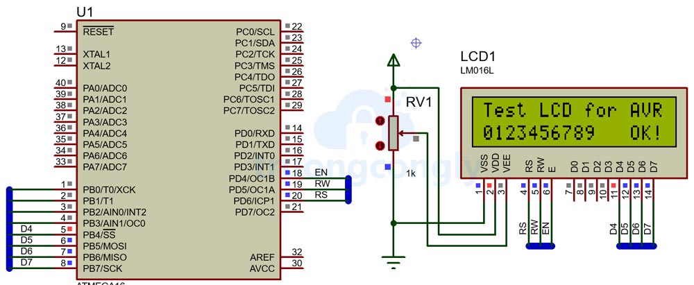
}Mạch mô phỏng ví dụ:
